
1998 Parker Fly Deluxe Repair - What a Mission
1998 Parker Fly Deluxe Repair – Circuit Board Diving
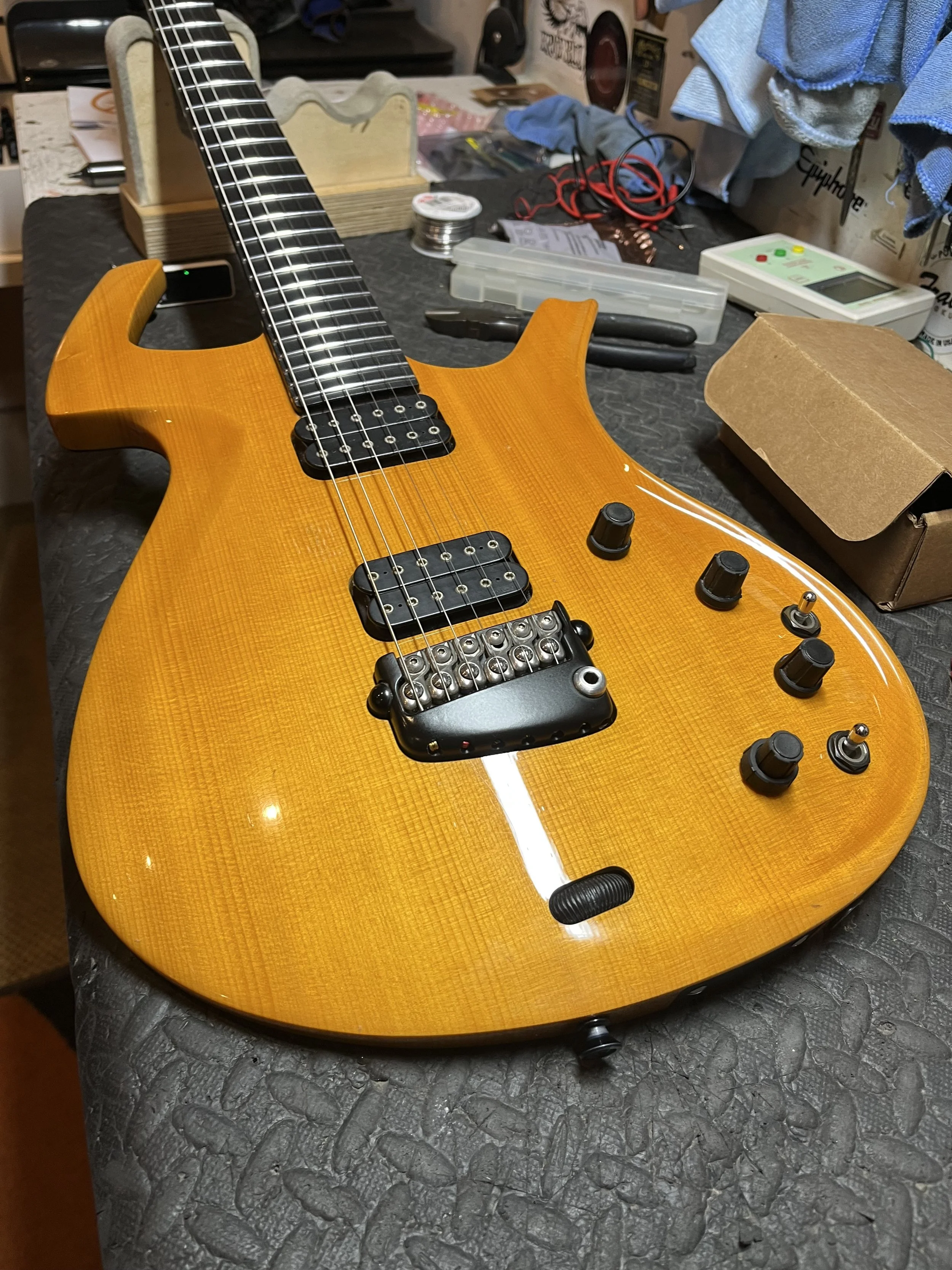
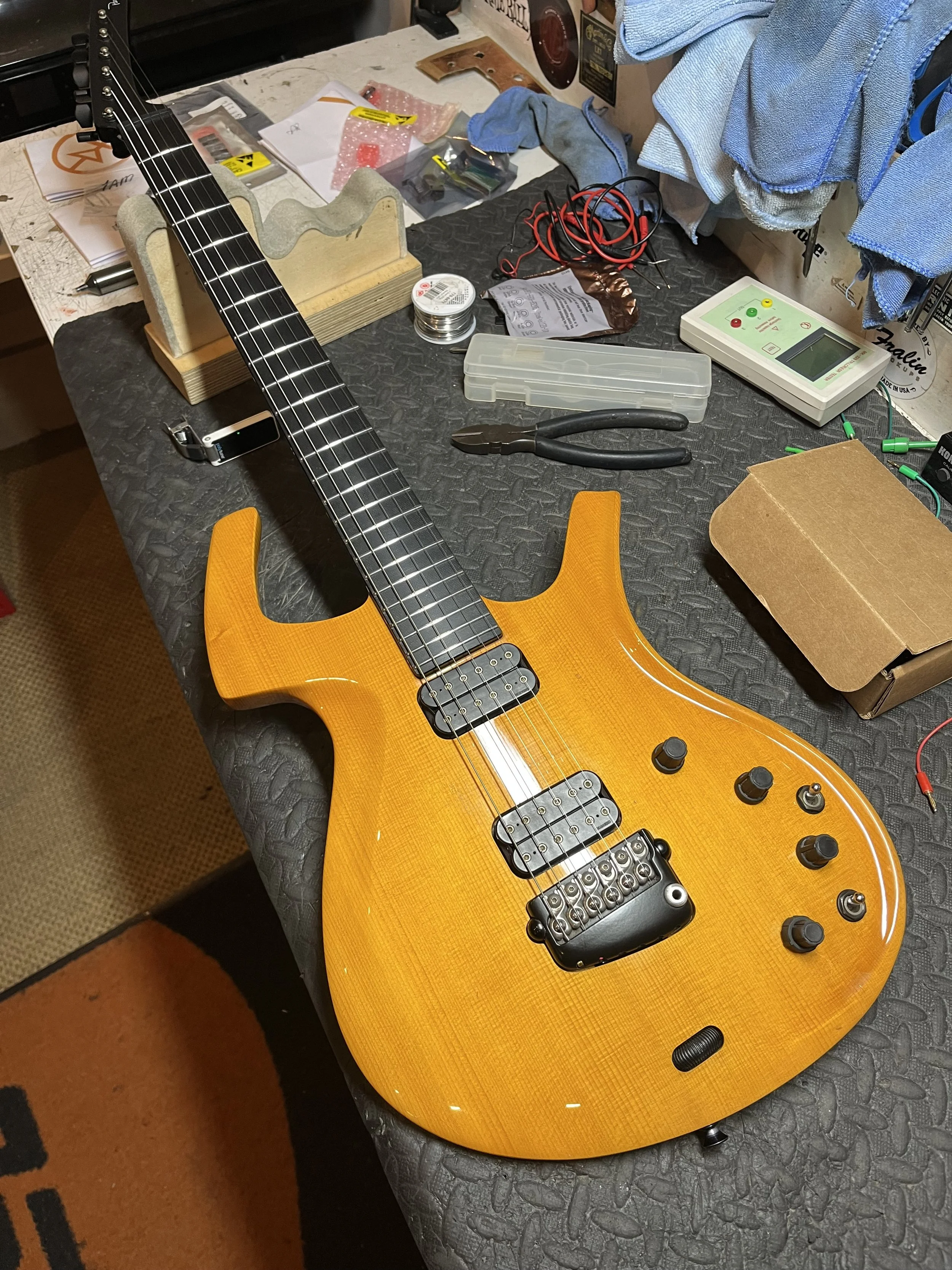
This job started out as something I’ve looked after dozens of times, a faulty input jack on a late-90s Parker Fly Deluxe.
However, on this particular model of guitar, it is never just a jack replacement. What followed turned into a full deep-dive into one of the more unusual and delicate electronic systems ever put into a production guitar. Designed by Ken Parker, the Fly was a genuinely forward-thinking instrument, and if you’re not familiar with Ken Parker’s designs, then now’s the time to find out! Carbon fibre reinforcement, ultra-light construction, and a hybrid magnetic/piezo system made it unlike anything else on the market at the time. When these came out in the 90’s, nobody had seen anything like it for sure.
They were certainly way ahead of their time, and as such, there are a lot of proprietary parts that were designed or modified specifically for this guitar. Specially adapted Dimarzio Pickups, Piezo-equipped tremolo bridge & electronics designed and made by Fishman, and a few other special appointments that require very specific tools, like the star key truss rod adjuster, jeeez. From a player’s perspective, it’s brilliant. From a repair perspective, it’s complicated.
The Electronics – This is Not Your Typical Guitar Circuit
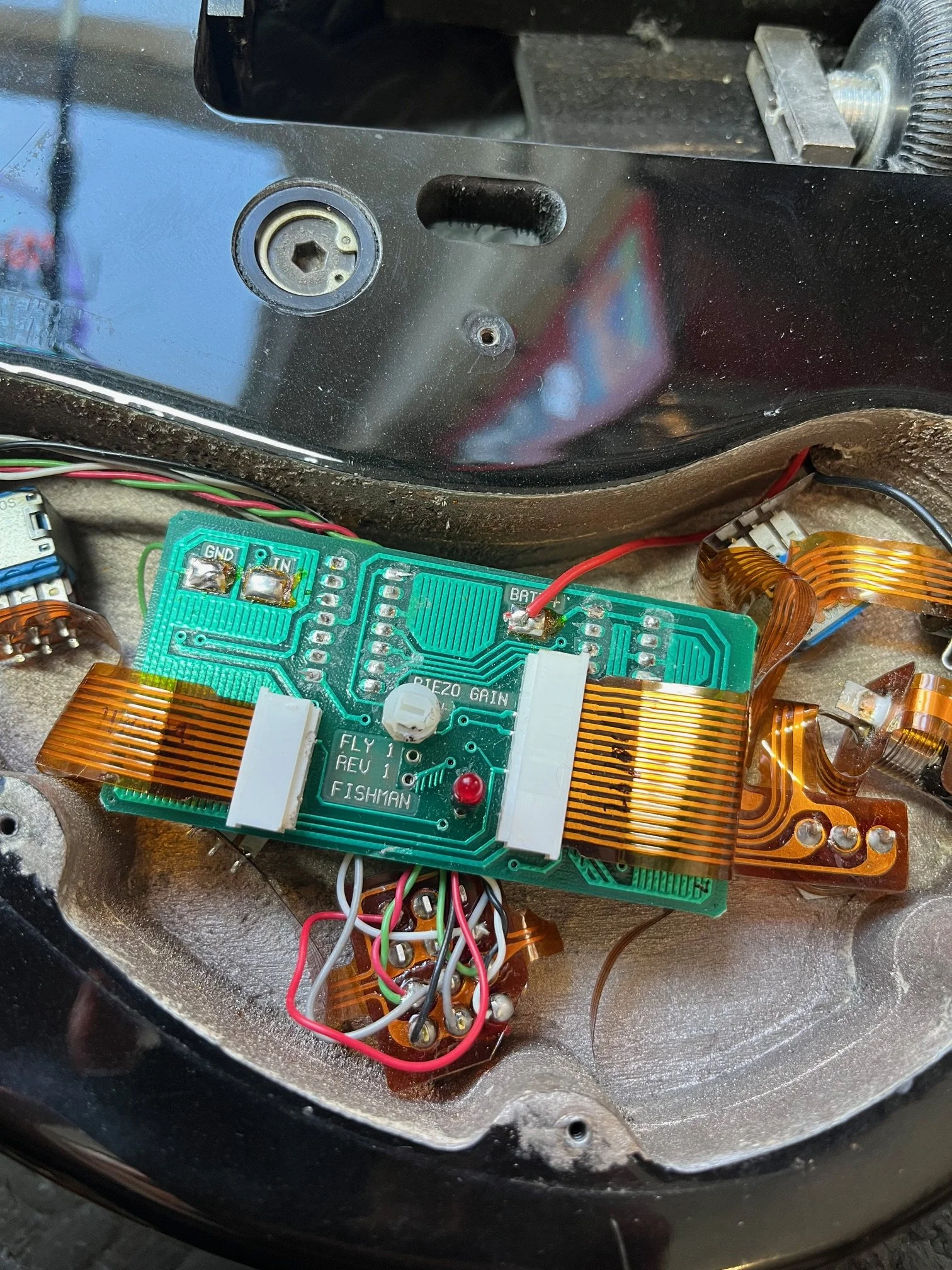
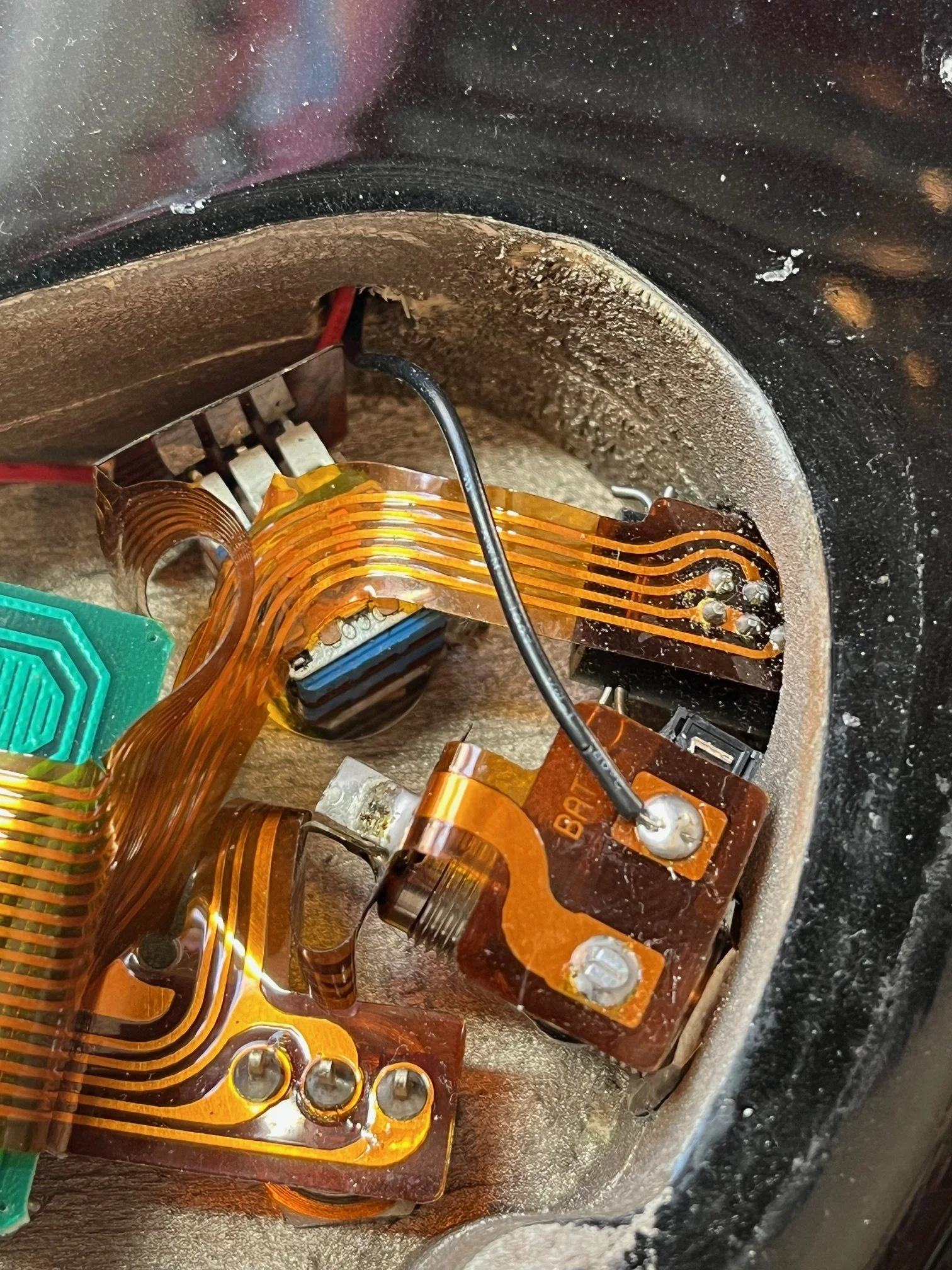
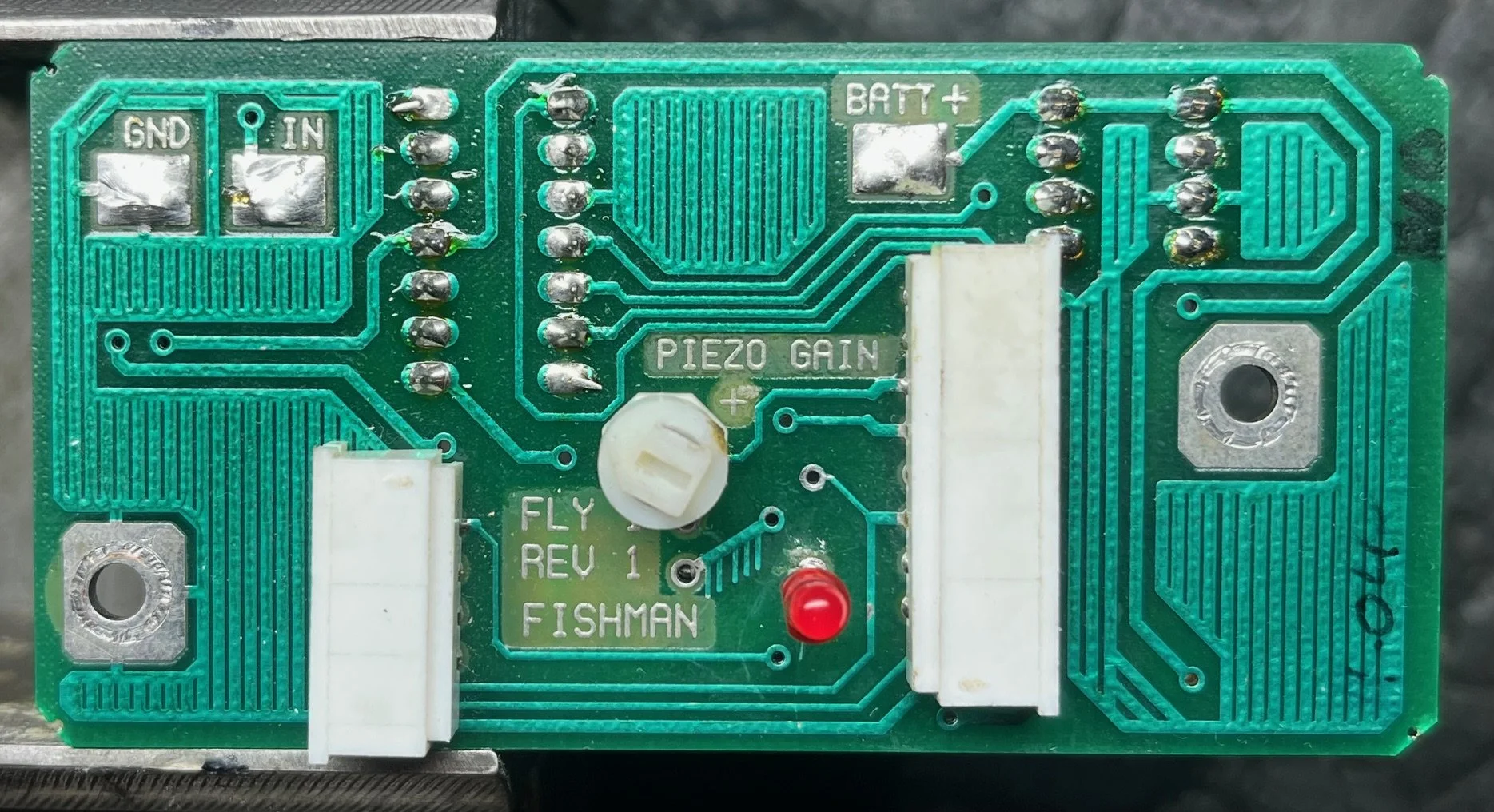
The Fly Deluxe combines passive magnetic pickups with an active piezo system, all managed by an onboard preamp. Crucially, much of this is handled via flexible printed circuits rather than conventional wiring.
That design keeps everything compact, but it also means the system is far less tolerant of age, handling, and component failure. When something goes wrong, we’re not just tracing wires; we’re interpreting a tightly integrated electronic system. This is further complicated now by the fact that nearly every mechanical component on the guitar has long since been discontinued and hasn’t been available for years. There are no parts, and technical information is in very short supply.
The Original Job – A “Simple” Jack
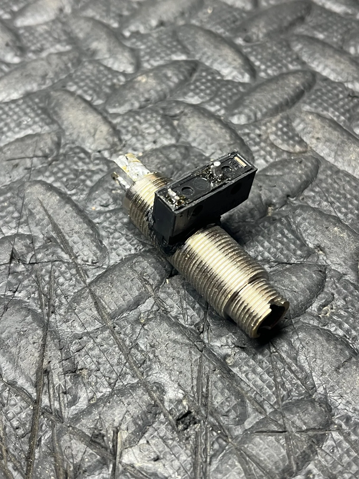
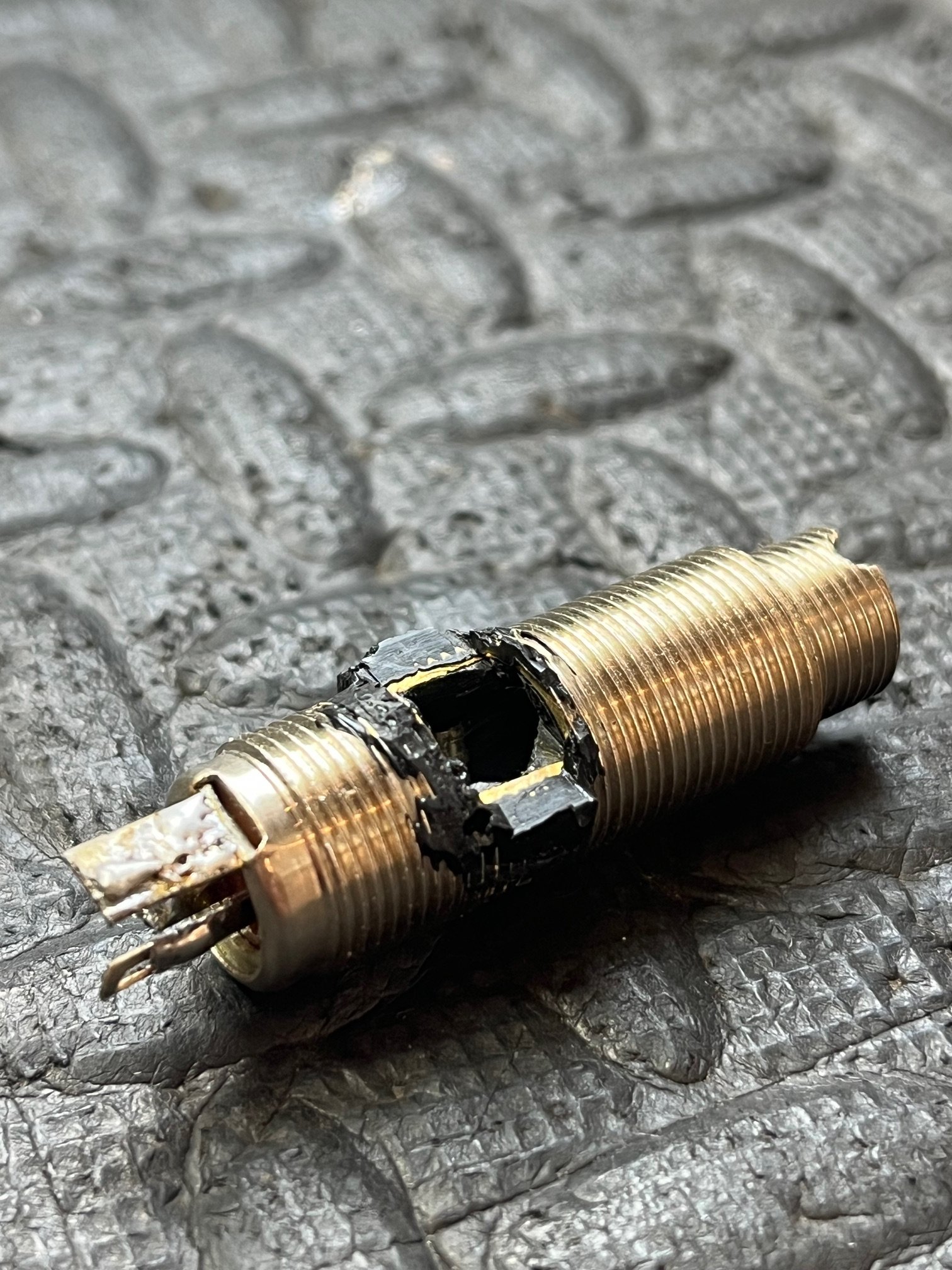
The guitar came in for a jack replacement. On a standard instrument, that’s a quick job. On a Fly, the jack is part of the power switching for the active circuit, so the replacement has to be modified, and an on/off function carefully integrated and secured in place. It’s already a job that requires patience. Nothing about it is plug-and-play. On the earlier Fly’s, the switch for the power is mounted into the side of the barrel jack, so when a lead is inserted, the tiny internal switch is engaged, running power into the circuit. This is basically thin plastic, and needs to be VERY carefully removed from the old, worn jack. On the new jack, a channel will need to be cut at precisely the right position, angle, and depth before the switch can then be epoxied back into the jack, and it can be installed into the guitar. It’s delicate and time-consuming, but done with patience and care, everything will be up and running again.
When It Failed
Now I’ve done this job a few dozen times over the years, so I know my way around things; however, despite taking the usual precautions (including ESD awareness and careful handling), the guitar went from partially working to completely dead during the process. No output at all, just unpleasant high-pitched squaling. At that point, the job shifts entirely. I’m no longer replacing a component; I’m diagnosing a complete circuit board failure. Deeper dive we go!
Fault Finding – Into the Circuit
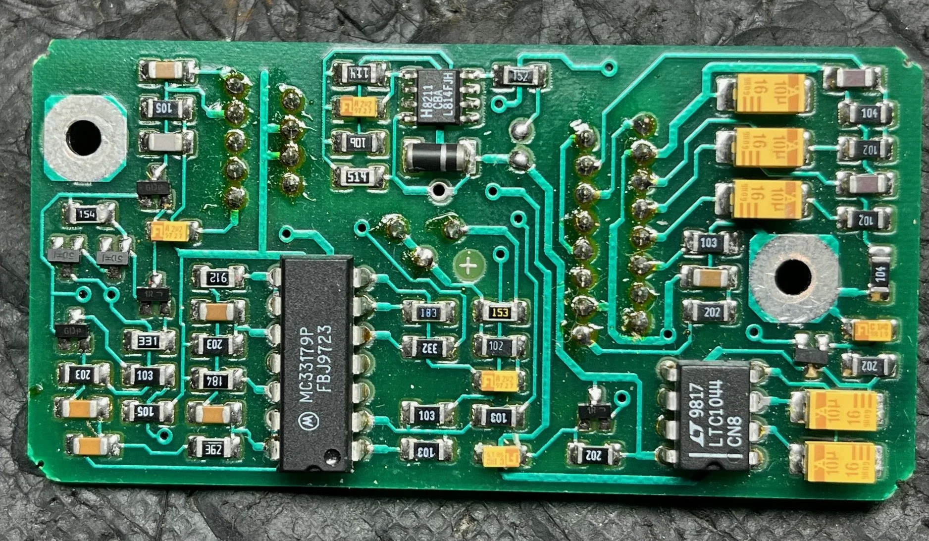
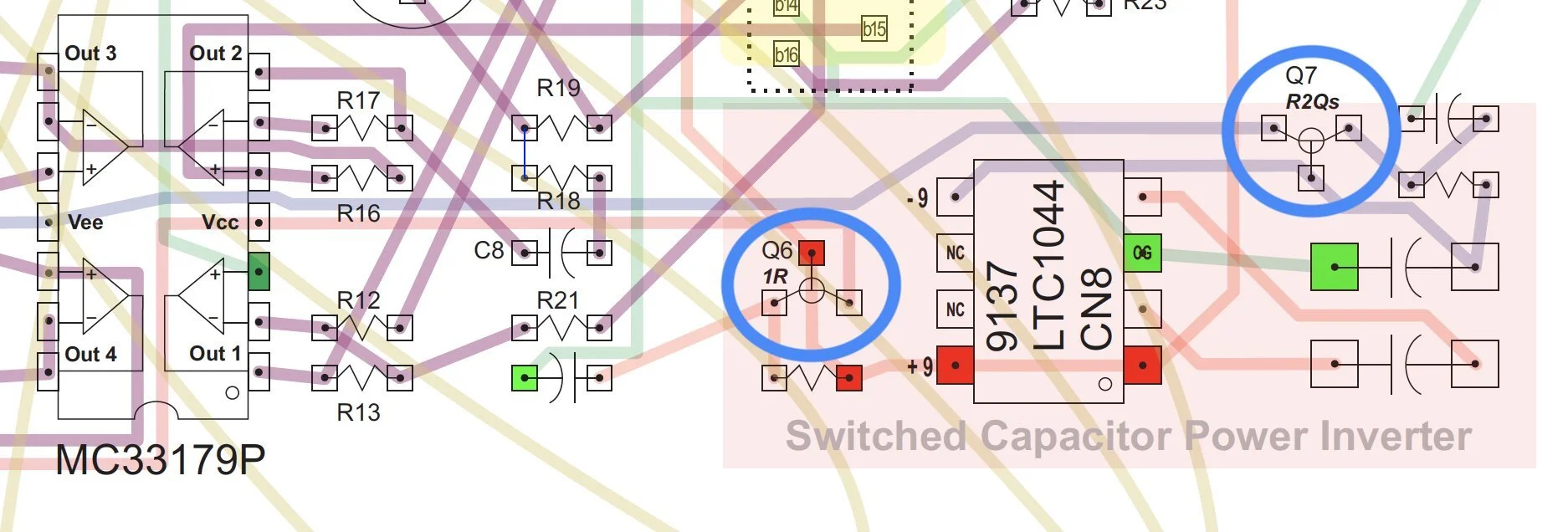
Tracing the circuit led fairly quickly to the power section of the preamp. The Parker Fly uses a charge pump IC, the LTC1044, to generate a negative voltage rail from the standard 9V supply. That negative rail is essential for the op-amp stage to function correctly.
In this case, that part had failed. The negative rail had effectively disappeared, which explains the total loss of signal. These chips are known to be somewhat delicate, so it wasn’t entirely surprising, but it did mean the job had escalated well beyond the original scope. Thankfully, these chips are still out there, and another was ordered.
Replacing the LTC1044 restored the positive and negative supply rails, which was a good sign, but the circuit still wasn’t behaving properly.
The Second Fault – Unstable Op-Amp Behaviour
Attention then turned to the main preamp chip, the MC33179P. Voltage readings across the outputs were inconsistent and didn’t line up with what you’d expect from a stable, balanced quad op-amp configuration. At that point, there were two likely possibilities: either the op-amp itself had failed, or something upstream in the power conditioning stage was causing it to behave incorrectly.
The chip was removed and tested in isolation. It turned out to be fine.
Which meant the problem was elsewhere.
The Real Culprit – Power Conditioning Stage
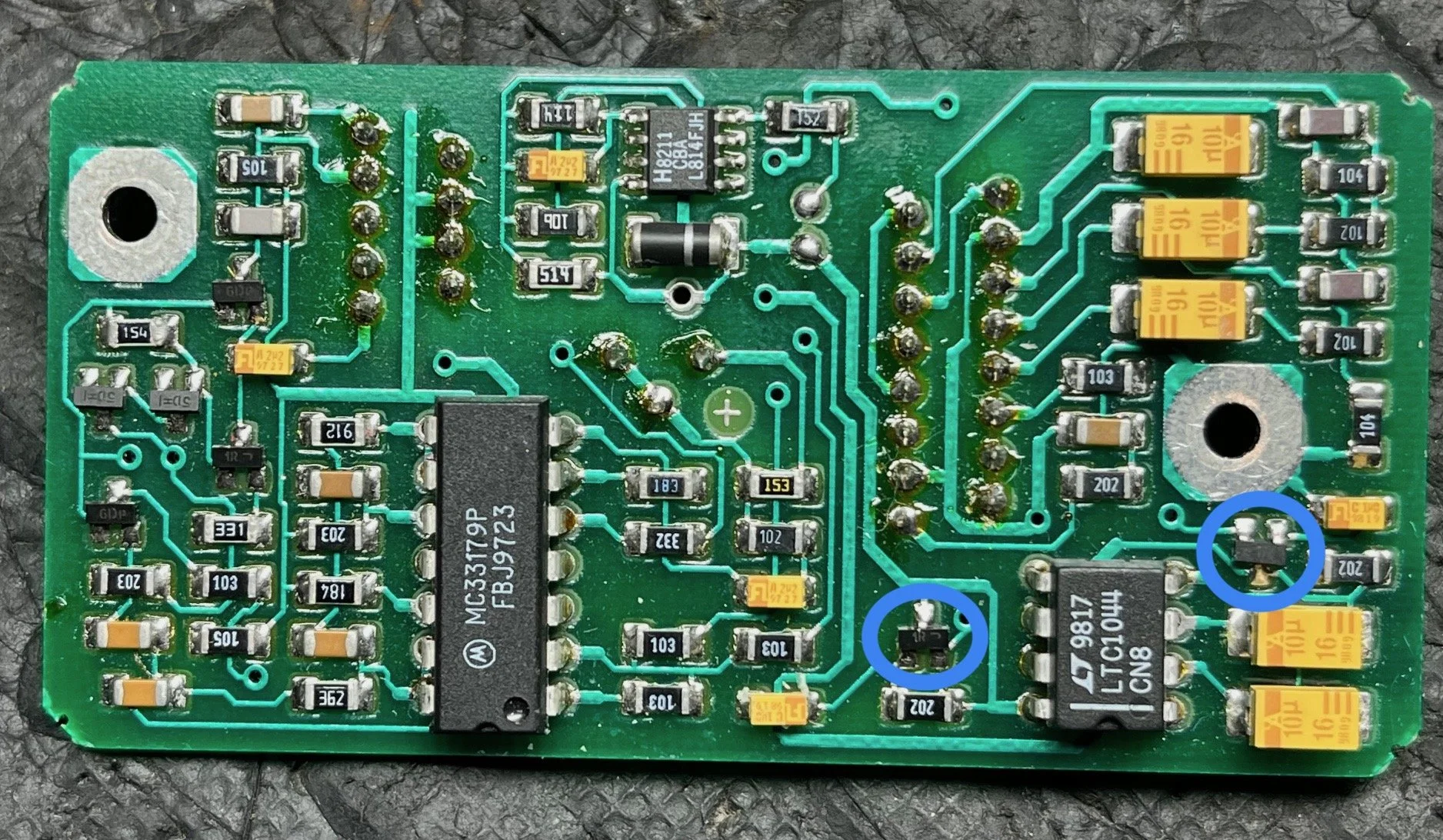
With the op-amp ruled out, focus shifted back to the section between the charge pump and the preamp. Specifically, the small transistor pair responsible for conditioning the supply.
These transistors (labelled Q6 and Q7 on the board) appear to act as a simple stabilisation and protection stage for the generated negative rail. In circuits like this, they help smooth behaviour during power-up and prevent irregularities from reaching sensitive components like the charge pump and op-amp.
In this case, the NPN transistor (Q6) had failed.
It wasn’t a dramatic failure, but enough to distort the voltage conditions feeding the op-amp. That’s why the readings looked ‘all over the place’ rather than simply dead; the circuit was powered, just incorrectly. It was also why no sound was coming out of the guitar at all, in any setting.
Replacing that transistor restored proper voltage balance across the circuit, and the system immediately returned to normal operation. I used some generic MMBT3904 & MMBT3906 transistors to complete this job, and although it’s not absolutely necessary, it is a good idea to replace both sides while at this sort of repair.
The Repair and Preventive Work
With the faulty transistor replaced and the charge pump already renewed, the board was reassembled and tested. Both the magnetic and piezo systems were functioning correctly again!
Two additional steps were taken: First, the LTC1044 was socketed. Given how sensitive those chips can be, it makes future servicing significantly easier if the same issue ever arises again. Second, I replaced the missing LED from the circuit board. It’s a mystery as to why it was not there (basically a low battery indicator), but it does make me a little suspicious about someone digging around in the circuit sometime before it made its way to me. All good though, and it works correctly now.
Looking at the sequence of events, this wasn’t a single-point failure but a chain:
The original jack issue led to disassembly and handling. That likely exposed or triggered a weak point in the power section, causing the LTC1044 to fail. Once that went, the supply rails collapsed. After replacing it, the underlying issue — the failing transistor — became apparent.
To round it all up
The Parker Fly Deluxe is an impressive design, but it’s also a good example of how complexity and age can combine to make relatively simple jobs far more involved.
What started as a jack replacement turned into power supply reconstruction, fault tracing across multiple stages, component-level repair of a non-standard circuit, and the annoying wait for replacement parts to arrive!
And that’s the reality of working on instruments like this. You’re not just fixing what’s obviously broken; sometimes, you’re dealing with everything that’s waiting to fail next. This nearly 30-year-old guitar should now be ‘flying’ again for years to come, plus there are some updated ideas in there to help with future work, should it ever need some
A mission, without question, but a satisfying one when it comes back to life properly. I’d also like to thank the excellent ‘Fly Clone Project’ website (https://flyclone.com/) for their passion for all things fly, as well as the section of technical documentation, including circuit breakdowns, that really helped with this repair!